Screenshots are embedded and scaled to 25% per the workflow.
Precision
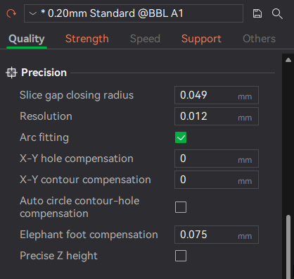
Quality tab → Precision (screenshot)
These settings control how closely the printed geometry matches the digital model, especially for curves, holes, and small dimensional details.
Slice gap closing radius
What it affects: Tiny gaps between adjacent extrusion paths.
Increase it when:
- You see small pinholes or gaps in top surfaces or thin walls
- You want cleaner-looking surfaces on cosmetic parts
Decrease it when:
- Fine details are getting blurred or overfilled
- Very small features are being lost
Example: A decorative box shows tiny gaps between lines on flat faces → slightly increase this value to visually close them.
Resolution
What it affects: How smoothly curves are approximated during slicing.
Increase it when:
- Circles or curves look faceted
- You’re printing parts with visible curved edges (vases, round housings)
Decrease it when:
- Slicing is slow or produces very large G-code files
- The model is mostly straight lines or mechanical geometry
Example: A round knob looks slightly polygonal → increase resolution for smoother curves.
Arc fitting
What it affects: Converts many short straight moves into true arcs.
Enable it when:
- Printing parts with lots of curves
- You want smoother motion and smaller G-code files
Disable it when:
- Troubleshooting unusual motion behavior
- Printing extremely precise mechanical parts where predictability matters
Example: A cylindrical part prints with subtle vibration marks → enabling arc fitting can smooth motion.
X–Y hole compensation
What it affects: The printed size of holes in the X–Y plane.
Increase it when:
- Screws, bolts, or pins don’t fit into holes
- Holes consistently print undersized
Decrease it when: Holes are coming out too loose.
Example: An M3 screw won’t pass through a printed hole → apply a small positive hole compensation instead of redesigning the model.
X–Y contour compensation
What it affects: The overall external size of the part.
Increase it when: Parts are consistently slightly too small.
Decrease it when: Parts are consistently slightly too large.
Example: A snap-fit box is just a bit too tight overall → a small contour compensation can correct it globally.
Auto circle contour–hole compensation
What it affects: Automatically applies different compensation logic to circular holes versus outer contours.
Enable it when:
- You want better dimensional accuracy without manual tuning
- Printing parts with many holes and circular features
Disable it when: You need full manual control for calibration or testing.
Example: A part with many different hole sizes prints inconsistently → enabling this can normalize results.
Elephant foot compensation
What it affects: Bottom-layer flare caused by heat and first-layer squish.
Increase it when:
- Bottom edges are wider than the rest of the part
- Parts don’t sit flat against mating surfaces
Decrease it when: The bottom edge looks undercut or weak.
Example: A box won’t slide into a slot because the bottom edge is too wide → increase elephant foot compensation.
Precise Z height
What it affects: Vertical dimensional accuracy.
Enable it when:
- Parts must match an exact height
- Layer stacking accuracy matters more than speed
Disable it when: Printing fast prototypes or when minor Z-height variation is acceptable.
Example: A printed spacer must be exactly 10 mm tall → enable precise Z height.
Precision – Quick Reference
| Setting | What it Fixes | Typical Adjustment | When to Touch It |
|---|---|---|---|
| Slice gap closing radius | Tiny gaps between lines | Small increase | Visible pinholes or gaps on surfaces |
| Resolution | Faceted curves | Increase | Circles or curves look polygonal |
| Arc fitting | Choppy motion on curves | Enable | Parts with many curves |
| X–Y hole compensation | Holes too tight | Small positive value | Screws/pins don’t fit |
| X–Y contour compensation | Part overall size | Small ± adjustment | Whole part too big or small |
| Auto circle contour–hole comp. | Inconsistent holes | Enable | Parts with many holes |
| Elephant foot compensation | Bottom edge flare | Increase gradually | Bottom edge wider than rest |
| Precise Z height | Incorrect height | Enable | Exact Z height required |
General tuning advice: Change one setting at a time, use small test prints (holes/cubes/rings), and prefer compensation settings over editing the model when the issue is repeatable.
Seam
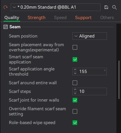
Quality tab → Seam (screenshot)

Seam position dropdown (screenshot)
These settings control where and how each layer starts and ends, which directly affects visible seam lines, surface quality, and strength at layer transitions.
Seam position
What it affects: Where the layer start/end seam is placed on the model.
Options explained:
- Nearest – Places seams close to the previous layer’s seam; fastest, but may create visible vertical lines.
- Aligned – Forces seams into a single vertical line; easy to hide on corners.
- Back – Attempts to place seams on the back side of the model relative to the camera.
- Random – Distributes seams randomly to avoid a single visible line.
Example: A decorative cylinder shows a single ugly seam → switch from Aligned to Random.
Seam placement away from overhangs (experimental)
What it affects: Prevents seams from being placed on overhanging areas where they are more visible or weaker.
Enable it when: seams look rough/droopy on angled surfaces or you have noticeable overhang seams.
Disable it when: you want full manual control or are troubleshooting seam placement.
Smart scarf seam application
What it affects: Replaces a hard seam start/stop with a gradual “scarf” transition.
Enable it when: you want the least visible seams possible (cosmetic prints).
Disable it when: printing fast prototypes or when maximum seam predictability is required.
Scarf application angle threshold
What it affects: Determines which angles qualify for scarf seam blending.
Increase it when: you want scarf seams applied more aggressively.
Decrease it when: seams start affecting sharp features.
Scarf around entire wall
What it affects: Applies scarf blending around the full wall instead of only at the seam location.
Enable it when: you want maximum seam hiding on high-finish parts.
Disable it when: you want minimal toolpath complexity.
Scarf steps
What it affects: How gradual the scarf transition is.
Increase it when: seams are still visible.
Decrease it when: surface detail is being softened.
Scarf joint for inner walls
What it affects: Applies scarf transitions to inner walls as well as outer walls.
Enable it when: internal appearance or strength matters.
Disable it when: inner walls are hidden and speed matters.
Override filament scarf seam setting
What it affects: Forces scarf seam behavior regardless of filament profile defaults.
Enable it when: filament defaults aren’t producing good seam results.
Role-based wipe speed
What it affects: Adjusts wipe behavior differently for walls, infill, and other roles.
Enable it when: seams show blobs or stringing.
Disable it when: diagnosing extrusion issues.
Seam – Quick Reference
| Setting | What it Fixes | Typical Choice | When to Touch It |
|---|---|---|---|
| Seam position | Visible seam line | Random / Aligned | Visible vertical seam |
| Away from overhangs | Rough seam on angles | Enable | Seams landing on overhangs |
| Smart scarf seam | Harsh seam start | Enable | Cosmetic prints |
| Scarf angle threshold | Scarf not triggering | Adjust | Scarf seams not being applied |
| Scarf around entire wall | Seam still visible | Enable | High-finish parts |
| Scarf steps | Abrupt transition | Increase | Seam still visible |
| Inner wall scarf | Internal seam marks | Enable | Internal strength/appearance |
| Override filament scarf | Filament mismatch | Enable | Filament-specific seam issues |
| Role-based wipe speed | Blobs at seam | Enable | Seam blobs/stringing |
Layer Height
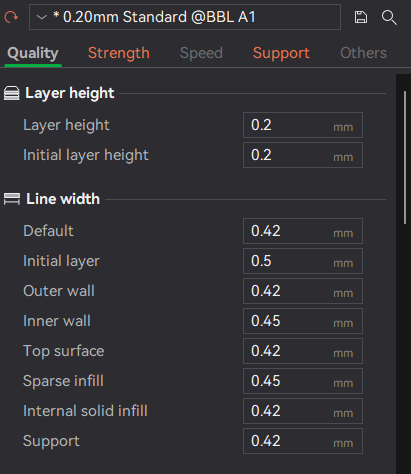
Quality tab → Layer height & Line width (screenshot)
These settings control vertical resolution, surface smoothness, and print time.
Layer height
Decrease it when: you want smoother surfaces or more visible detail (decorative parts).
Increase it when: you want faster prints (large functional parts).
Example: A figurine shows visible layer lines → reduce layer height.
Initial layer height
Increase it when: adhesion is inconsistent or your first layer needs more tolerance for bed variation.
Decrease it when: you need fine detail on the bottom surface.
Example: A part lifts at the corners → increase initial layer height slightly.
Line Width
These settings control how wide each extrusion line is, affecting strength, surface finish, and dimensional accuracy.
Default line width
Increase it when: you want stronger parts and can accept slightly less detail.
Decrease it when: fine detail matters.
Initial layer line width
Increase it when: prints have adhesion issues.
Outer wall line width
Decrease it when: fine external detail and dimensional accuracy matter most.
Inner wall line width
Increase it when: structural strength is important.
Top surface line width
Decrease it when: top surfaces look rough or uneven.
Sparse infill line width
Increase it when: faster prints are preferred over fine infill detail.
Internal solid infill line width
Controls the strength of solid internal layers.
Support line width
Decrease it when: supports are hard to remove.
Note: Line width is a “feel” setting—small changes can have big effects. If you’re tuning, adjust one item at a time and test on a small part.
Screenshot index
If you need to move these into your repo assets folder, these are the paths referenced by this page:
assets/images/process-settings/quality/quality-precision.pngassets/images/process-settings/quality/quality-seam.pngassets/images/process-settings/quality/quality-seam-position-dropdown.pngassets/images/process-settings/quality/quality-layer-height-line-width.png